Introduction
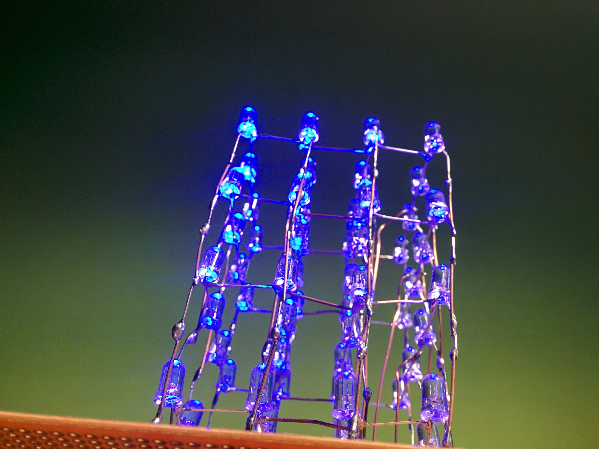
For this project I wanted to create a three-dimensional LED cube that could be controlled by an Arduino microcontroller. The cube consists of 64 LED’s arranged into 4 layers. The 16 LED’s in each layer are soldered into a 4 by 4 grid. After this the Arduino was connected to the cube so that it could control the voltage and ground connections to the rows and columns of the cube. This allowed the Arduino to produce a series of patterns and displays on the cube.
How does it work?
The LED’s are soldered together so that all of the LED’s in a row share a common cathode. An additional wire is soldered onto each row and it connects each row to a ground pin (0v) on the Arduino (4 in total). All of the LED’s in a column share a common anode and the columns are connected to pins on the Arduino that act as VCC (5v) (16 in total). As a result only 20 pins are required to control all of the LED’s in the cube then the 64 pins otherwise if each LED was connected individually.
In order to turn a single LED on I needed to supply ground to that layer and 5v to the other three layers. I also need to supply 5v to the column that the LED was in and ground to the other 15 pins. As a result, individual rows, columns and LED’s could be lighted up at any one point. However a problem arises if you want to turn on 2 LED’s that are located at different positions in different columns. The diagram below helps to illustrate this.


Project Build
The pictures and text below show the process of the cube being built:
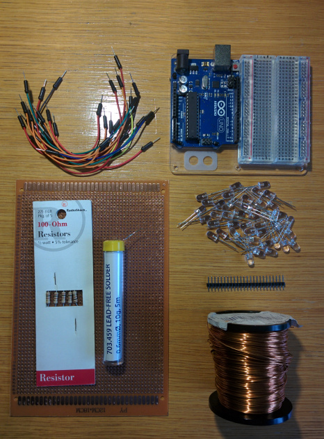
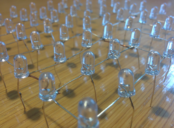
The image above shows the components that were used in order to make the cube. These were:
- x64 – LED’s
- x4 – 100 Ohm Resistors
- x1 - Pin Header
- Jumper Wires
- Solder
- Perf Board
- Arduino
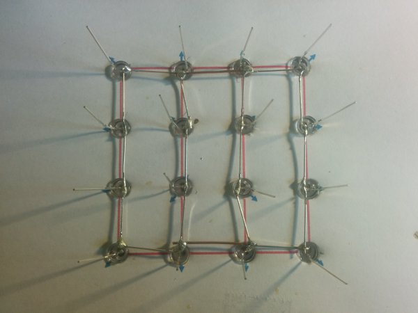
To start the project I printed a sheet of paper with the formatting of the LED legs and stuck that onto a piece of cardboard. I then pierced holes in the cardboard and stuck the top of the LED’s through. After this I soldered the cathode legs of the LED’s together while leaving the anode leg pointing upwards.

I did this process four times for each of the layers.

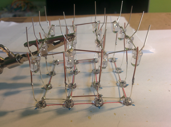
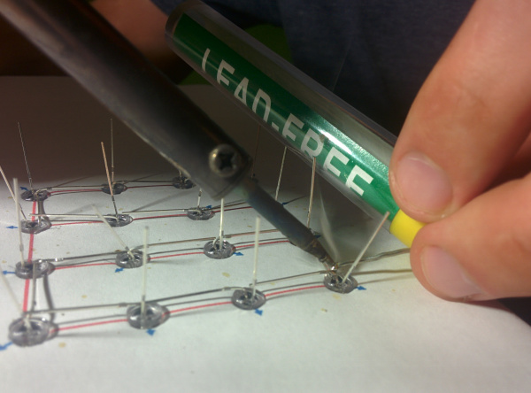
Following this I started to solder the individual layers together. I needed to solder on an extra wire to the anode of each LED so that the spacing between the individual LED layers was large enough for the structure to resemble a cube shape. I used a crocodile clip to hold individual wires and layers in place so that I could solder them.

The process was repeated two more times as the layers were soldered together.

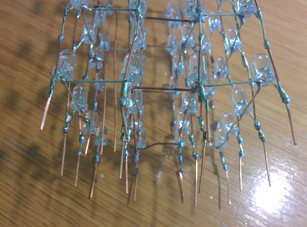
I soldered wires from each layer down to the base to act as the ground connections between each layer and the Arduino. In addition I soldered some extra wire onto the end of each column so that the legs of the structure were long enough to fit through the prototype board (which acts as a base).


The pictures above show the structure of the cube after it was soldered together.

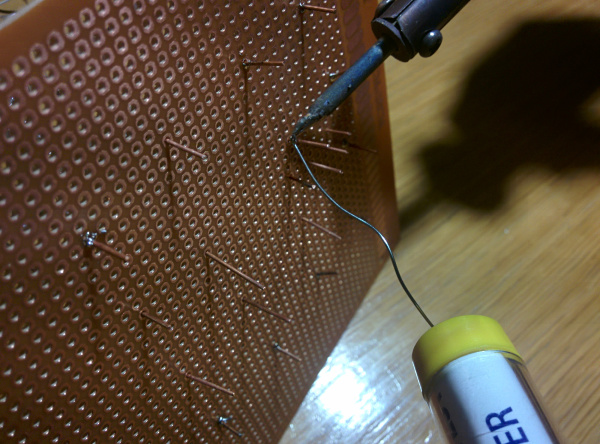
The legs of each column were carefully placed through the board and the were then soldered to it with excess wire being cut off.

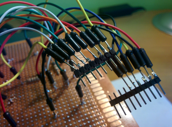
Four resistors were attached to the ground columns and jumper wires were connected to each column and row connection. The jumper wires were then soldered to three header pins to make it easier to connect to the Arduino.


The code was then uploaded to the Arduino and the power was turned on.

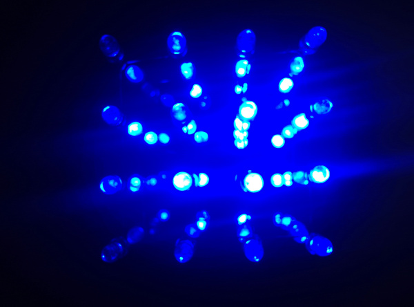
Lights out; Party Power on!
Project Build
- The anode leg of each LED was not long enough for the layers to be soldered together to resemble a cubic shape. As a result I soldered an extra wire onto the end of each leg to increase the distance between layers.
- The solution above created an additional problem which was that the previous soldered connection between the leg and the extra wire heated up and became loose as I soldered two layers together. To solve this I created a greater overlap between soldered wires so that the connection was stronger.
Coding the Cube!
After downloading code to make patterns and effects on the cube, I decided to write a couple of my own sequences. The first pattern that I programmed was the effect of lighting up the outer LED’s in a circular pattern from bottom to top and then doing that to the inner LED’s as well but lighting them up from top to bottom. The video below shows this:
The code below shows how this was programmed (the Arduino IDE uses elements of C and C++ to program the microcontroller):
void Loopallleds()
{
  //Creating an array of the outside LED's
  int outisdeloop[12] = {0,1,2,3,7,11,15,14,13,12,8,4};
  //Creating an array of the inside LED's
  int insideloop[4] = {5,6,10,9};
  //Delays in the program (in ms)
  int delay1 = 15;
  int delay2 = 25;

  //This function turns all of the LED's off.
  AllLedsOff();

  //Loops four times for all of the layers
    for(int j = 3; j >= 0; j--)
    {
      digitalWrite(layer[j], 1);
      //Loops around all of the outside LED's turning them on and then off.
      for(int i = 0; i < 12; i++)
      {
        digitalWrite(column[array[i]], 0);
        delay(delay1);
        digitalWrite(column[array[i]], 1);
        delay(delay1);
      }
      digitalWrite(layer[j], 0);
    }

    //Loops around all of the inside LED's turning them on and then off.
    for(int j = 0; j < 4; j++)
    {
      digitalWrite(layer[j], 1);
      for(int i = 0; i < 4; i++)
      {
        digitalWrite(column[array2[i]], 0);
        delay(delay2);
        digitalWrite(column[array2[i]], 1);
        delay(delay2);
      }
      digitalWrite(layer[j], 0);
    }
}
Another pattern that I decided to program was to have each layer of the cube flash on from bottom to top. After this the LED’s would create a rain effect as the columns were turned off in series. This can be seen in the video below with the code for it beneath that:
void Layersflashandfall()
{
  //Delays in the program (in ms)
  int delay1 = 100;
  //This array stores the column numbers of the cube
  int allcolumns[16] = {0, 1, 2, 3, 4, 5, 6, 7, 8, 9, 10, 11, 12, 13 ,14, 15};
  //Maximum index number of the array
  int arrindex = 15;
  //Size of the array
  int arrsize = 16;

  //Loops through all four of the layers turning them off
  for(int i = 0; i < 4; i++)
  {
    digitalWrite(layer[i], 0);
  }

    //Loops through all of the layers.
    for(int i = 4; i !=0; i--)
    {
      //Flashes the layer on quicker increments
      int delvar = 150;
      while (delvar != 0)
      {
        digitalWrite(layer[i-1], 1);
        delay(delvar);
        digitalWrite(layer[i-1], 0);
        delay(delvar);
        delvar -= 15;
      }
      //Keeps the layer lit up after it has flashed on
      if (i == 4)
      {
        digitalWrite(layer[i-1], 1);
      }
      else if (i == 3)
      {
        digitalWrite(layer[i-1], 1);
      }
      else if(i == 2)
      {
        digitalWrite(layer[i-1], 1);
      }
      else
      {
        digitalWrite(layer[i-1], 1);
      }
    }

  delay(500);

  //Turns all of the LED's off
  AllLedsOff();

  //Produces the rain effect 16 times as one LED is removed each time
  for(int i = 0; i != 16; i++)
  {
    //Turns all of the columns on
    for(int p = 0; p < arrindex; p++)
    {
      digitalWrite(column[p], 0);
    }

    //Turns on the top LED of each column and the one below it adding,
    //a delay afterwards to create the rain effect.
    digitalWrite(layer[0], 1);
    delay(delay1+50);
    digitalWrite(layer[0], 0);
    digitalWrite(layer[1], 1);
    delay(delay1);
    digitalWrite(layer[1], 0);
    digitalWrite(layer[2], 1);
    delay(delay1);
    digitalWrite(layer[2], 0);
    digitalWrite(layer[3], 1);
    delay(delay1+50);
    digitalWrite(layer[3], 0);

    //Turns all of the columns off
    for(int p = 0; p < arrindex; p++)
    {
      digitalWrite(column[p], 1);
    }

    //Turns a random column off by removing a column from the array.
    int randomColumn = random(0,arrsize);
    for(int i = 0; i < arrsize; i++)
    {
      if(allcolumns[i] == randomColumn)
      {
        for(int j = i; j < arrsize; j++)
        {
          allcolumns[j] = allcolumns[j+1];
        }
        arrsize--;
      }
    }
    arrindex--;
  }
}