Introduction
A binary clock displays the time in a similar fashion to a digital clock. It does this by using 4 LED columns where the two left hand columns show the hour digits and the two right hand columns show the minute digits. The 4 columns use a total of 13 LED’s with different columns requiring different amounts of LED’s. Similarly to the LED cube, the clock is also programmed with the Arduino microcontroller.
How does it work?
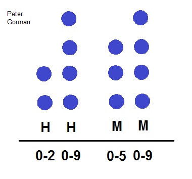
Before explaining how the clock works I will start by explaining how the clock is to be read. The binary clock has 4 columns as shown in the diagram below, 2 to show the hour and 2 to show the minute. The number of LED’s required by each digit is determined by the range of possible values that the digit could be. For a 24 hour clock, the first hour hand could be either a 0, 1 or 2 for example at times 09:10, 15:20 and 21:30. As a result there needs to be enough LED’s to represent a 3 numbers and therefore only 2 LED’s (or bits) are required. These are 00 (no LED’s on) to show 0, 01 (bottom LED on) to show 1, 10 (top LED on) to show 2 and 11 (both LED’s on) which is not used. In this case 11 is left unassigned as there wont be a need for the number 3 for the first hour hand. The other digits follow a similar pattern but require different amounts of bits. The other hour hand and the rightmost minute hand both require 4 bits to represent the digits from 0 to 9. The first minute hand needs 3 bits to represent the digits from 0 to 5.
In order to turn a single LED on I needed to supply ground to that layer and 5v to the other three layers. I also need to supply 5v to the column that the LED was in and ground to the other 15 pins. As a result, individual rows, columns and LED’s could be lighted up at any one point. However a problem arises if you want to turn on 2 LED’s that are located at different positions in different columns. The diagram below helps to illustrate this.
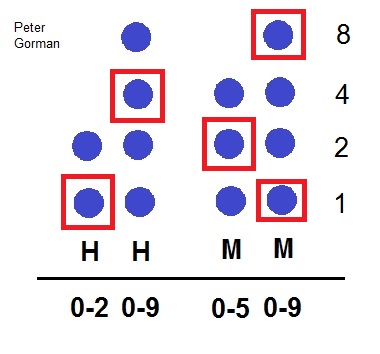
Using the image below as an example, the time can be easily read using the numbers (which show the number of bits) next to the minute hands digit. The left most column is represented by a 1. The column next to it is a 4 and the one next to that is a 2. Finally the last column has 2 LED’s that are on so the numbers add, 8 + 1 = 9. As a result the time is therefore: 14:29
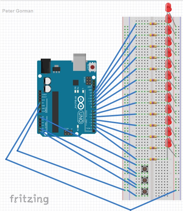
The circuit was connected as shown in the diagram below. Each LED is connected in series with a resistor and in parallel with every other LED. All of the LED’s are aligned so that they are connected to the 5v pin on the Arduino. In addition the negative end of the LED links each resistor to a pin on the Arduino so that each LED can be programmed individually. The three push buttons are connected to the analogue inputs of the Arduino and also ground. One of the push buttons can increase the minutes and another the hours so that the time can be set. With each push of the button the value increases by one in binary on the display. The third push button turns all of the LED’s either on or off depending on their current state.
Project Build
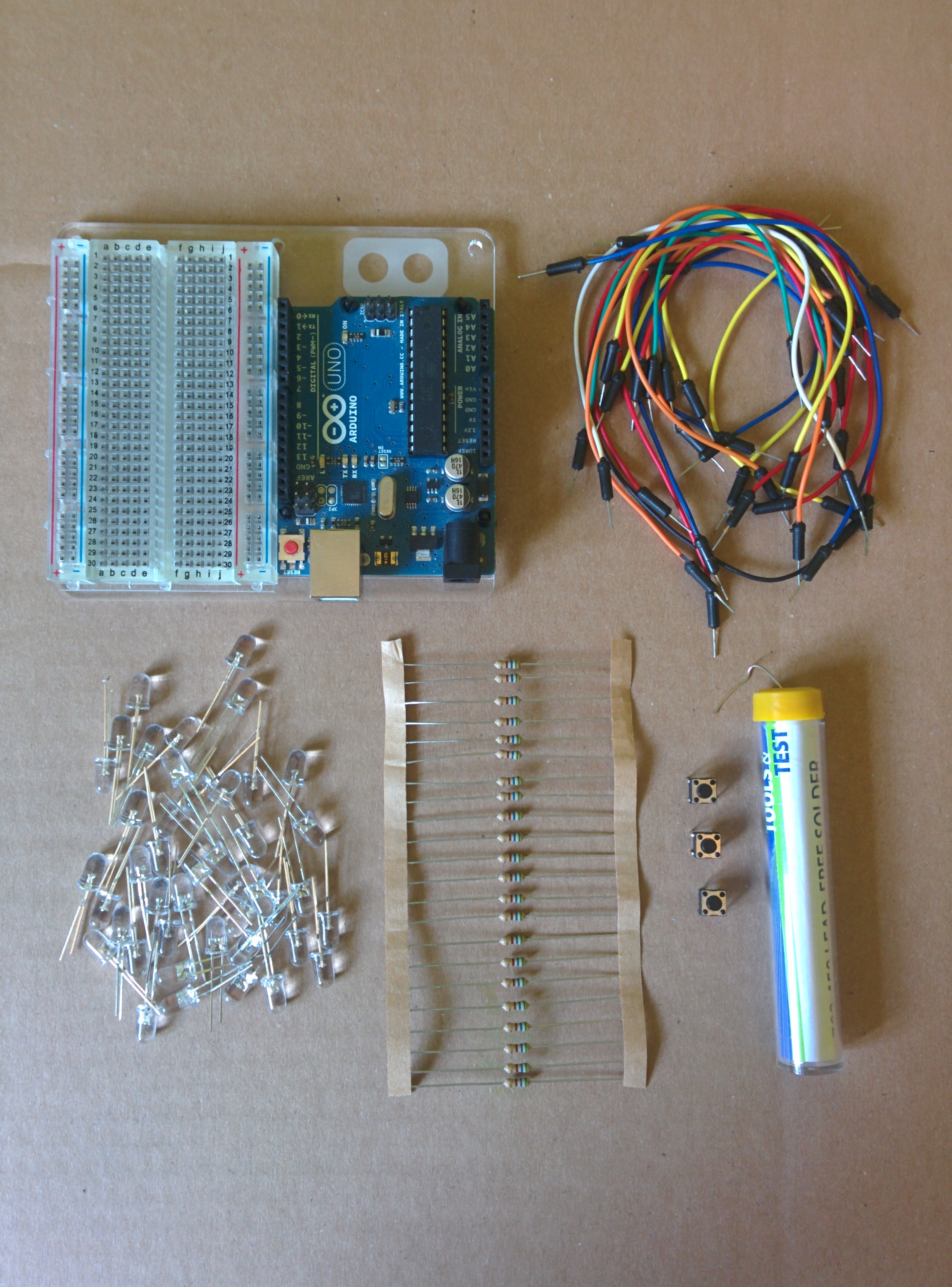
The image above shows the components that were used in order to make the clock. These were:
- x13 – LED’s
- x13 – 560 Ohm Resistors
- x3 Push Buttons
- Jumper Wires
- Solder
- Cardboard
- Bell Wire
- Arduino

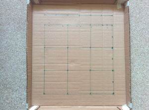
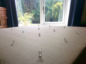
To begin the project I marked a 4 by 4 grid on a piece of cardboard so that the LED’s were evenly placed in a structured format. I also folded and taped the edges of the cardboard so that components of the clock could be hidden and so that the clock could be hung on a wall.
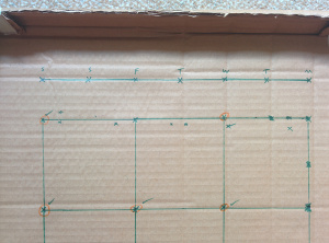
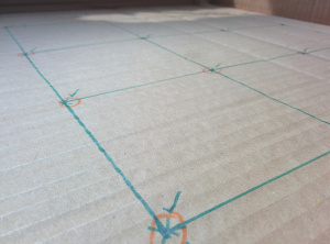
Following that I marked which holes were to have LED’s placed through them.
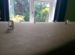
I made holes for the legs of the LED’s to fit through so that the head of the

Next I used a hot glue gun on each of the LED’s to keep them in place when they were soldered and also for when the clock is hung on a wall.
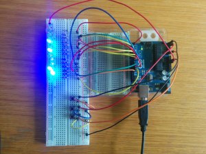
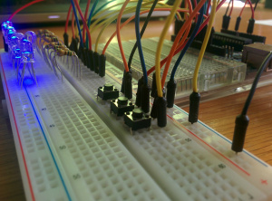
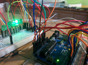
Before soldering the components in place and completing the circuit I built a trial of the circuit on a Breadboard as shown in the pictures above.
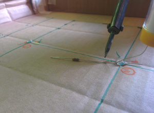

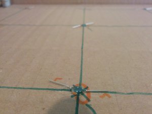
The negative leg of each LED was soldered to a resistor.


The positive legs of all of the LED’s were connected together using jumper wires.

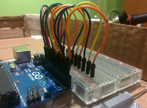
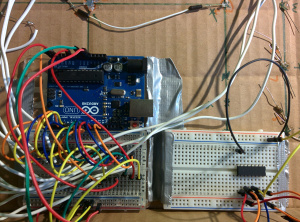
I stuck the Arduino onto the cardboard and put jumper wires from the digital pin connections and onto an adjacent Breadboard.

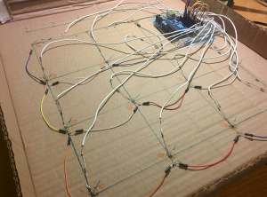
I then stripped several lengths of bell wire and soldered that between each resistor and corresponding Breadboard hole.

Finally I added the three push buttons to control the minute LED’s, the hour LED’s and one to switch the LED’s on and off. I also connected the 5v pin from the Arduino to the LED’s.

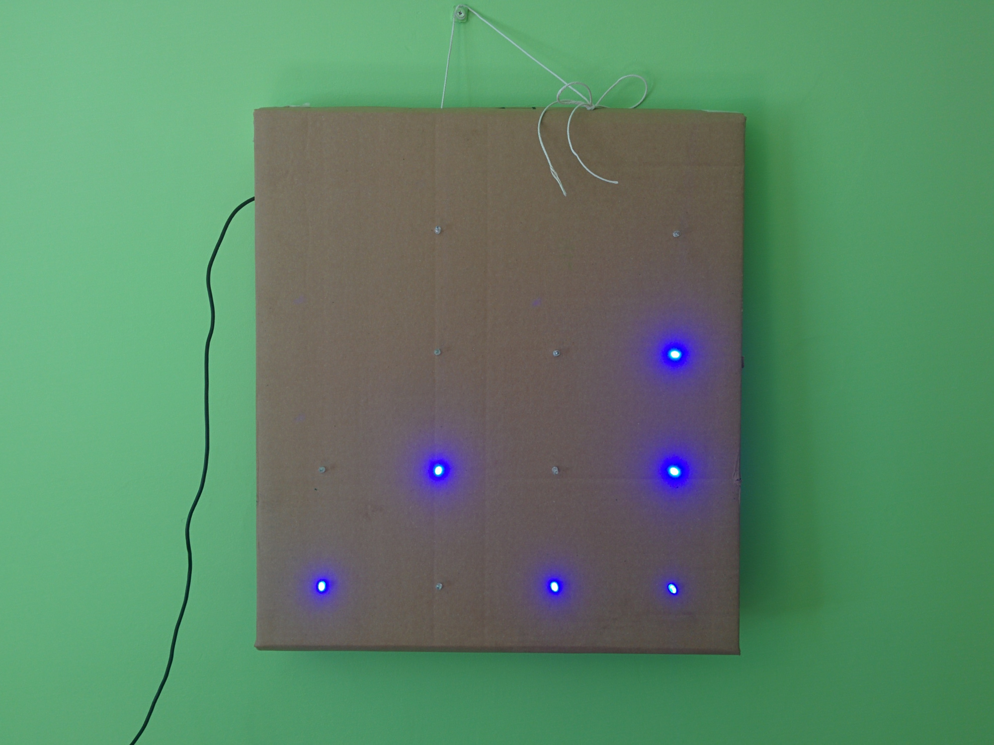
The code was then uploaded to the Arduino and the clock was hung on the wall. Time is ticking!
Adding days of the week!
After completing the clock I wanted to improve it by adding an extra set of LED’s to show which day of the week it was. However I only had three I/O pins left on the Arduino but I needed an extra seven to control each day. To solve this problem I started to look at shift registers and in particular the 74HC595 chip.
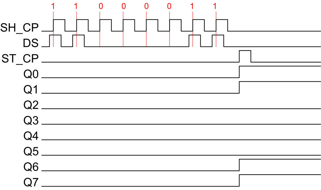
The 595 chip allows 8 outputs to be controlled while only taking up 3 input pins on the Arduino. These three pins are called the data pin (DS), clock pin (Sh_CP) and latch pin (ST_CP). When the clock pin pulses the value on the data pin is stored as either a 1 (high) or 0 (low). During this process the Latch pin is held low while the eight values are written to the shift register (writing over the previous stored bits). Afterwards the latch pin goes to high and it outputs the stored bits to Q0-Q7. It does this so that the LED’s come on without a flickering effect. This can be seen in the diagram below:

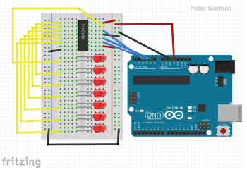
http://ba.protostack.com/2010/05/shift_register_10_lrg.jpg The circuit diagram below shows the setup of the shift register with the LED’s and Arduino.
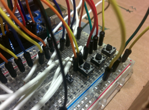
The pictures below show how this part of the project was assembled:
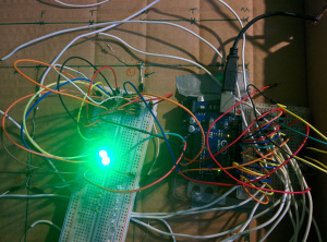
The circuit was tested on a Breadboard to check that the LED’s operated as expected.


The LED’s were stuck into the cardboard and resistors were added to the negative leg of the LED’s as before.

The chip was placed onto the Breadboard and that was stuck to the cardboard frame. It was then wired up to the Ardunio and LED’s


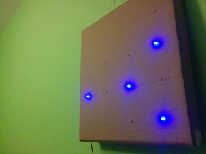
The finished clock is shown above! The green LED’s represent the weekdays starting from monday on the far left. The red LED’s represent the weekend.
The code below shows the addition part that I added in order to control the days of the week LED’s with the on/off push button:
//Creating variables to store which day of the week it is.
int minute = 0;
int hour = 0;
int day = 0;
int daychange = 0;
//Variables to store the I/O pin of the 595 chip.
int clockPin = 16;
int dataPin = 17;
int latchPin = 15;

//Pattern array to turn a single LED on at a time
byte pattern[7] = {
B00000001,
B00000010,
B00000100,
B00001000,
B00010000,
B00100000,
B01000000,
//B10000000, Last bit is not used
};

//Setting the variables to outputs
void setup()
{
pinMode(latchPin, OUTPUT);
pinMode(clockPin, OUTPUT);
pinMode(dataPin, OUTPUT);
}

//Loop segment of the code
void loop()
{

//After 24 hours the day counter moves forward and the hour and minute are reset
if (hour >= 24)
{
    day++;
    hour = 0;
    minute = 0; // reset minutes to zero
}

//After seven days have passed the day is reset to Monday
if (day >= 7)
{
    day = 0;
}

//Changing the bit pattern sent to the Arduino
digitalWrite(latchPin, LOW);
shiftOut(dataPin, clockPin, MSBFIRST, patterns[day]);
digitalWrite(latchPin, HIGH);

//Reads the input from a push button and increases the day of the week accordingly without
//changing the hour or minute.
daychange = digitalRead(18);
if (daychange == LOW)
{
    day++;
    second = 0;
delay(250);
}
}
Adding days of the week!
- An alarm system that flashes the LED’s that are currently on at a specified time could be a future implementation to the clock. In addition a piezo buzzer could serve as an audio aid for the alarm.